How to Configure VLANs and Trunk Port on Cisco Switch
 Suresh Thapa
VLAN :- A VLAN is a group of devices on one or more LANs that are configured to communicate as if they were attached to the same wire, when in fact they are located on a number of different LAN segments. Because VLANs are based on logical instead of physical connections, they are extremely flexible.
Layer 2 switches create broadcast domains based on the configuration of the switch. Switches are multiport bridges that allow you to create multiple broadcast domains. Each broadcast domain is like a distinct virtual bridge within a switch.
You can define one or many virtual bridges within a switch. Each virtual bridge you create in the switch defines a new broadcast domain (VLAN). Traffic cannot pass directly to another VLAN (between broadcast domains) within the switch or between two switches. To interconnect two different VLANs, you must use routers or Layer 3 switches. Configuration of Layer 3 Interfaces (SVI)
Trunk Port :- A trunk port is a port that is assigned to carry traffic for all the VLANs that are accessible by a specific switch, a process known as trunking. Trunk ports mark frames with unique identifying tags – either 802.1Q tags or Inter-Switch Link (ISL) tags – as they move between switches. ISL Inter-switch link is a Cisco proprietary it means it is available only Cisco switches. 802.Q1 open standard trunking protocol this protocol can use anyone. If you have two different vendor switches example Cisco and Juniper you have to use 802.Q1 trunking protocol.
For this lab I am using EVE-NG Community Version and IOSv-L2
Task:
Change you Hostname
SW1, SW2, SW3
Create the following VLANs and configure the correct names:
VLAN 10: name Management.
VLAN 20: name Admin.
VLAN 30: name IT.
VLAN 40: name Accounts.
- Configure Gi0/2 on SW1 as an access interface in VLAN 10.
- Configure Gi0/3 on SW1 as an access interface in VLAN 20.
- Configure Gi1/0 on SW1 as an access interface in VLAN 30.
- Configure Gi0/2 on SW2 as an access interface in VLAN 10.
- Configure Gi0/3 on SW2 as an access interface in VLAN 20.
- Configure Gi1/0 on SW2 as an access interface in VLAN 30.
- Configure Gi0/2 on SW3 as an access interface in VLAN 10.
- Configure Gi0/3 on SW3 as an access interface in VLAN 20.
- Configure Gi1/0 on SW3 as an access interface in VLAN 30.
- All of the links between switches make trunk ports and should use dot1q encapsulation.
Topology for this Task
_HmJZxjV.jpg)
Switch-1
Change Hostname
Switch(config)#hostname SW1
Create VLANs
SW1(config)#vlan 10
SW1(config-vlan)#name Management
SW1(config)#vlan 20
SW1(config-vlan)#name Admin
SW1(config)#vlan 30
SW1(config-vlan)#name IT
SW1(config)#vlan 40
SW1(config-vlan)#name Accounts
Configure Access Ports
SW1(config)#interface gigabitEthernet 0/2
SW1(config-if)#switchport mode access
SW1(config-if)#switchport access vlan 10
SW1(config-if)#no shutdown
SW1(config-if)interface gigabitEthernet 0/3
SW1(config-if)#switchport access vlan 20
SW1(config-if)#switchport mode access
SW1(config-if)#no shutdown
SW1(config-if)interface gigabitEthernet 1/0
SW1(config-if)#switchport mode access
SW1(config-if)#switchport access vlan 30
SW1(config-if)#no shutdown
Configure Trunk Ports
SW1(config)#interface gigabitEthernet 0/0
SW1(config-if)#switchport trunk encapsulation dot1q
SW1(config-if)#switchport mode trunk
SW1(config-if)#no shutdown
SW1(config)#interface gigabitEthernet 0/1
SW1(config-if)#switchport trunk encapsulation dot1q
SW1(config-if)#switchport mode trunk
Sw1(config-if)#no shutdown
Save Configuration
SW1#copy running-config startup-config
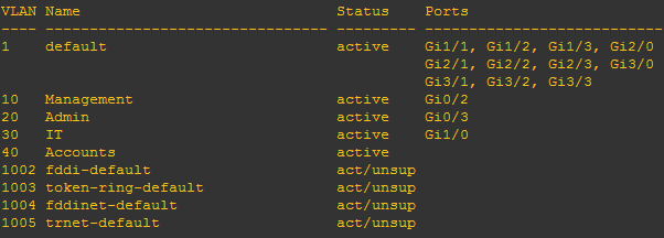
Verify your VLANs, Trunk and Access port.
Sw1#show vlan
Sw1#show interface trunk

Switch-2
Change Hostname
Switch(config)#hostname SW2
Create VLANs
SW2(config)#vlan 10
SW2(config-vlan)#name Management
SW2(config)#vlan 20
SW2(config-vlan)#name Admin
SW2(config)#vlan 30
SW2(config-vlan)#name IT
SW2(config)#vlan 40
SW2(config-vlan)#name Accounts
Configure Access Ports
SW2(config)#interface gigabitEthernet 0/2
SW2(config-if)#switchport mode access
SW2(config-if)#switchport access vlan 10
SW2(config-if)#no shutdown
SW2(config-if)interface gigabitEthernet 0/3
SW2(config-if)#switchport access vlan 20
SW2(config-if)#switchport mode access
SW2(config-if)#no shutdown
SW2(config-if)interface gigabitEthernet 1/0
SW2(config-if)#switchport mode access
SW2(config-if)#switchport access vlan 30
SW2(config-if)#no shutdown
Configure Trunk Ports
SW2(config)#interface gigabitEthernet 0/0
SW2(config-if)#switchport trunk encapsulation dot1q
SW2(config-if)#switchport mode trunk
SW2(config-if)#no shutdown
SW2(config)#interface gigabitEthernet 0/1
SW2(config-if)#switchport trunk encapsulation dot1q
SW2(config-if)#switchport mode trunk
SW2(config-if)#no shutdown
Save Configuration
SW2#copy running-config startup-config
Verify your VLANs, Trunk and Access port.
SW2#show vlan
Sw2#show interface trunk
Switch-3
Change Hostname
Switch(config)#hostname SW3
Create VLANs
SW3(config)#vlan 10
SW3(config-vlan)#name Management
SW3(config)#vlan 20
SW3(config-vlan)#name Admin
SW3(config)#vlan 30
SW3(config-vlan)#name IT
SW3(config)#vlan 40
SW3(config-vlan)#name Accounts
Configure Access Ports
SW3(config)#interface gigabitEthernet 0/2
SW3(config-if)#switchport mode access
SW3(config-if)#switchport access vlan 10
SW3(config-if)#no shutdown
SW3(config-if)interface gigabitEthernet 0/3
SW3(config-if)#switchport access vlan 20
SW3(config-if)#switchport mode access
SW3(config-if)#no shutdown
SW3(config-if)interface gigabitEthernet 1/0
SW3(config-if)#switchport mode access
SW3(config-if)#switchport access vlan 30
SW3(config-if)#no shutdown
Configure Trunk Ports
SW3(config)#interface gigabitEthernet 0/0
SW3(config-if)#switchport trunk encapsulation dot1q
SW3(config-if)#switchport mode trunk
SW3(config-if)#no shutdown
SW3(config)#interface gigabitEthernet 0/1
SW3(config-if)#switchport trunk encapsulation dot1q
SW3(config-if)#switchport mode trunk
SW3(config-if)#no shutdown
Save Configuration
SW3#copy running-config startup-config
Verify your VLANs, Trunk and Access port.
SW2#show vlan
Sw2#show interface trunk
Right click on VPCS PCs and start and access console then configure IP on both PCs
Check connectivity using ping command.
PC1> ip 192.168.10.2/24 192.168.10.1
PC1> ip 192.168.10.3/24 192.168.10.1