How to Configure Switch Virtual Interface (SVI) as a Layer 3 Interface on Cisco Switch
 Suresh Thapa
A Switched Virtual Interface (SVI) is a VLAN of switch ports represented by one interface to a routing or bridging system. There is no physical interface for the VLAN and the SVI provides the Layer 3 processing for packets from all switch ports associated with the VLAN.
SVIs are generally configured for a VLAN for the following reasons:
- Allow traffic to be routed between VLANs by providing a default gateway for the VLAN.
- Provide Layer 3 IP connectivity to the switch.
- Support bridging configurations and routing protocol.
SVIs advantages include:
- Much faster than router on a stick, because everything is hardware-switched and routed.
- No need for external links from the switch to the router for routing.
- Latency is much lower because it does not need to leave the switch.
To configure Switch Virtual Interface (SVI) I will use IOSv-L2 on EVE-NG. How to configure IOSv-L2 on GNS3 for advanced Switching.
TASK
- Create VLANs 10, 20, 30 and 20
Configure all IP addresses as specified.
SW1: VLAN-10 - 192.168.10.1/24, VLAN-20 - 192.168.20.1/24, VLAN-30 - 192.168.30.1/24, VLAN-40 - 192.168.40.1/24,
SW2: VLAN-10 - 192.168.10.2/24
SW3: VLAN-10 - 192.168.10.3/24
- Configure SW1 SVI Interface for all the VLANs and configure IP address.
- Configure PC1 in VLAN 20 and PC2 in VLAN 30.
- Ensure PC1 and PC2 are able to communicate with each other.
Topology for this Task
_HmJZxjV_1HJNPx5.jpg)
Create VLANs on all switches
SW1(config)#vlan 10
SW1(config-vlan)#name Management
SW1(config-vlan)#exit
SW1(config)#vlan 20
SW1(config-vlan)#name Admin
SW1(config)#vlan 30
SW1(config-vlan)#name IT
SW1(config)#vlan 40
SW1(config-vlan)#name Accounts
SW1(config-vlan)#exit
Create SVI Interfaces on SW1
SW1(config)#interface vlan 10
SW1(config-if)#ip address 192.168.10.1 255.255.255.0
SW1(config-if)#no shutdown
SW1(config-if)#interface vlan 20
SW1(config-if)#ip address 192.168.20.1 255.255.255.0
SW1(config-if)#no shutdown
SW1(config-if)#ip address 192.168.30.1 255.255.255.0
SW1(config-if)#no shutdown
SW1(config-if)#interface vlan 20
SW1(config-if)#ip address 192.168.40.1 255.255.255.0
SW1(config-if)#no shutdown
Make all Switch to Switch link Trunk as on Topology Example below
SW(config)#interface gigabitEthernet <inteface no>
SW(config-if)#switchport trunk encapsulation dot1q
SW(config-if)#switchport mode trunk
SW(config-if)#no shutdown
Make Members of VLANs PC1 and PC2
SW2(config)#interface gigabitEthernet 0/2
SW2(config-if)#switchport mode access
SW2(config-if)#switchport access vlan 20
SW2(config-if)# no shutdown

SW3(config)#interface gigabitEthernet 0/2
SW3(config-if)#switchport mode access
SW3(config-if)#switchport access vlan 30
SW3(config-if)# no shutdown
Create SVI Interfaces on SW2 and SW3 for VLAN-10 only.
SW2
SW2(config)#interface vlan 10
SW2(config-if)#ip address 192.168.10.2 255.255.255.0
SW2(config-if)#no shutdown
SW3
SW2(config)#interface vlan 10
SW2(config-if)#ip address 192.168.10.3 255.255.255.0
SW2(config-if)#no shutdown
Create a default route on SW2 and SW3 pointing to SW1 VLAN 10 SVI interface so that both the switched can forward traffic coming from any VLANs.
SW(config)#ip default-gateway 192.168.10.1
Configure PC1 and PC 2 Ip addresses
PC1> ip 192.168.10.2/24 192.168.10.1
PC2> ip 192.168.20.2/24 192.168.20.1
Check connectivity
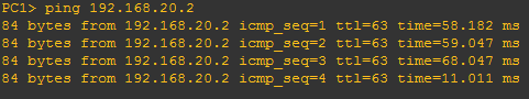
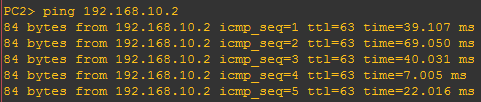
Congratulations: You have configured SVI successfully.